Views: 0 Author: Site Editor Publish Time: 2026-09-29 Origin: Site
Alluvial tin processing presents a persistent operational challenge for mine operators globally. Cassiterite possesses a high specific gravity ranging between 6.8 and 7.1. However, the mineral is also highly brittle. Aggressive physical handling easily reduces this valuable resource to ultra-fine slime. Once pulverized, these heavy fines wash out alongside waste tailings.
Selecting the right machinery solves only half your problem. You must arrange these units in a highly specific sequence. The exact sequential arrangement dictates your final yield. It determines whether a plant achieves a mediocre 60% recovery or an impressive 90% capture rate of fine particles ranging from -2mm to +0.02mm. Improper layouts guarantee massive financial losses.
This guide provides a pragmatic, decision-stage framework. You will learn how to configure a plant layout effectively. We explore proven methods to maximize fine tin recovery. Following these principles prevents over-capitalizing on unnecessary machinery while significantly boosting your final mineral yield.
Effective fine cassiterite recovery requires strict particle sizing prior to separation; feeding mixed sizes into a single separator guarantees fine tin loss.
A standard high-yield arrangement follows a specific gravity circuit: jigs for roughing, spirals for scavenging, and shaking tables for final cleaning.
Procurement evaluation must prioritize modularity, water efficiency, and the ability to process clay-heavy alluvial wash.
No commercial equipment layout should be finalized without prior metallurgical bench testing of the specific ore body.
Understanding the geological and physical realities of cassiterite is essential. Natural alluvial transport constantly grinds the mineral against harder riverbed rocks. This constant friction over-crushes the brittle cassiterite before mining even begins. Consequently, the deposit naturally contains high proportions of ultra-fine particles. Many legacy operations rely entirely on standard sluice-only setups. These basic setups create excessive water velocity. Fast-moving water lacks the precision needed to capture microscopic fines. The stream simply sweeps the valuable cassiterite away into the waste pile.
Misaligned equipment sequences create severe operational bottlenecks. Two primary failure modes occur during processing. First, "locking" happens when tin remains trapped inside uncrushed silica matrices. Second, "sliming" occurs when aggressive processing over-grinds the liberated tin. Both scenarios directly impact your bottom-line profitability. They artificially depress your overall resource yield. You lose saleable product every hour the plant operates improperly.
A viable processing circuit must meet three specific success criteria. First, you need high volumetric capacity at the initial roughing stage. Second, the circuit requires highly precise hydraulic classification. Third, you must incorporate low-velocity final cleaning stages. These deliberate design choices allow you to capture the highly profitable -0.5mm fraction successfully. Ignoring these criteria guarantees poor returns on your initial capital investment.
Designing a high-yield recovery plant requires integrating specialized alluvial tin mining equipment. Each machine performs a strictly defined role based on particle size.
Raw alluvial ore rarely arrives clean. It usually contains heavy clay matrices enclosing the valuable minerals. Trommel scrubbers or rotary screens break up these alluvial clays thoroughly. They aggressively wash the raw feed material. This crucial first step discards barren oversized gravel early in the process. Removing oversize rocks protects downstream machinery from catastrophic impact damage. It also frees the trapped cassiterite for efficient gravity separation.
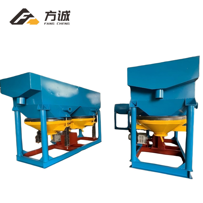
The tin ore jig concentrator handles the bulk primary separation. It plays a critical role in processing coarse-to-medium fractions. These fractions typically range from +2mm down to -10mm. The jig utilizes a pulsating water bed. This pulsation stratifies the material based on specific gravity. Heavy tin sinks through the screen bed. Lighter silica washes over the top into the tailings chute.
Operators value jigs for their exceptionally high throughput. They also offer a very low operational cost per ton. When evaluating a jig, you must examine the diaphragm stroke adjustability. Precise stroke control allows operators to fine-tune the suction phase. Furthermore, you should evaluate the screen bed wear life. Durable screens reduce maintenance downtime significantly.
The tin ore spiral chute serves as an exceptional scavenging unit. It handles medium-to-fine fractions highly efficiently. These units operate using simple centrifugal force and gravity. They contain zero moving mechanical parts. Slurry flows down the helical path. Heavy minerals hug the inner radius. Lighter waste flushes toward the outer edge.
Procurement decisions depend heavily on the spiral profile. The pitch and profile configuration must match your ore precisely. You must account for the specific gravity differential of the host rock. Spirals are absolutely critical for high-volume scavenging. They maintain a very low physical footprint while capturing escaping mid-range tin.
For ultimate precision, operators rely on the tin ore shaking table. This machine is the definitive tin gravity separation equipment for cleaning phases. It excels at recovering ultra-fine cassiterite. The effective recovery range spans from -2mm down to a microscopic 0.037mm.
Shaking tables provide relatively low processing capacity. However, they deliver extreme separation precision. The asymmetrical motion separates minerals across the riffled deck smoothly. Operators use tables to upgrade rough concentrates. This step achieves the final commercial grade required by smelters. A properly tuned table often produces concentrates exceeding 60% Sn.
Individual machines cannot perform miracles alone. You must arrange them into a logical, sequential flowsheet. Proper structuring maximizes recovery while minimizing water and energy usage.
Raw ore requires immediate washing and disintegration. You must separate the washed slurry into strict size brackets. Mixed particle sizes ruin gravity separation efficiency. Common target brackets include +2mm, 0.5-2mm, and -0.5mm fractions. Operators use hydraulic classifiers or high-frequency screens to achieve this separation. Strict classification prevents fine heavy particles from behaving like large light particles in the water flow.
Once classified, route the larger material fractions to the jig circuits. The jig handles the heavy lifting for volume reduction. The pulsating action quickly separates the coarse heavy minerals. Tailings from this stage are usually barren enough to send directly to waste. The resulting concentrate moves forward. Depending on liberation levels, this concentrate moves to a grinding circuit or goes directly to final cleaning.
Finer material requires different fluid dynamics. Route the -2mm material fractions to the spiral banks. Spirals handle high volumes of dilute slurry perfectly. This stage captures escaping fines originating from the primary wash. If you skip this step, these valuable fines flow directly into the tailings pond. Spirals act as an affordable safety net for your valuable fine particles.
The final stage focuses on purity. Feed the upgraded concentrates from both the jigs and spirals onto the shaking tables. Table setup varies based on your operational goals. Arrange tables in parallel if you need maximum processing capacity. Arrange them in series if you demand maximum concentrate grade. A series setup routes roughing table concentrates onto a dedicated cleaning table for perfect refinement.
Table 1: Equipment Processing Capabilities Comparison
Equipment Type | Optimal Particle Size Target | Volumetric Capacity | Primary Flowsheet Role |
|---|---|---|---|
Trommel Scrubber | Raw Feed (All Sizes) | Very High | Disintegration & Washing |
Jig Concentrator | +2mm to -10mm | High | Coarse Roughing |
Spiral Chute | -2mm to +0.1mm | Medium | Fine Scavenging |
Shaking Table | -2mm to 0.037mm | Low | Precision Cleaning |
Purchasing processing equipment involves significant capital risk. You must evaluate potential vendors using strict technical criteria. Do not rely solely on basic equipment brochures.
Every ore body possesses unique physical characteristics. You must ask vendors detailed technical questions. Do they provide equipment tailored to your specific particle size distribution (PSD) report? Avoid vendors selling generalized, off-the-shelf units. An effective manufacturer analyzes your ore sample first. They will adjust spiral pitches, jig screen sizes, and table riffle designs to match your exact mineralogy. Generic equipment always guarantees sub-optimal recovery rates.
Mining environments destroy poorly built machinery quickly. You must assess construction materials rigorously.
Spirals: Examine the surface lining. Fiberglass combined with a polyurethane lining vastly outperforms standard rubber. Polyurethane offers superior wear resistance against highly abrasive silica sand. This extends the operational lifespan of the spiral significantly.
Shaking Tables: Analyze the deck material. Fiberglass reinforced plastic (FRP) decks resist warping and water damage much better than traditional wood. Furthermore, the manufacturer must customize the riffle design specifically for heavy minerals like cassiterite.
Gravity circuits are exceptionally water-intensive operations. You cannot simply dump used water. You must evaluate the capital expenditure required for supporting infrastructure. Modern plants require thickeners to settle out fine mud. You will need hydrocyclones for dewatering concentrates. High-capacity water recycling pumps are mandatory to sustain the equipment line. A cheap machine becomes highly expensive if it requires twice the normal water volume to operate effectively.
Chart: Typical Water to Solid Ratio in Gravity Circuits
■ Roughing Jigs: ~2.5 m³ water per ton of feed
■ Spiral Chutes: ~3.0 m³ water per ton of feed
■ Shaking Tables: ~4.5 m³ water per ton of feed
Note: Values fluctuate based on exact feed density and clay content.
Even the best equipment fails if implemented poorly. Operators must understand common pitfalls before finalizing plant designs.
The most common failure occurs during Stage 1. Inadequate clay scrubbing ruins downstream efficiency. Sticky clay coats the fine cassiterite particles completely. This clay jacket alters the particle's apparent specific gravity. The heavy tin suddenly acts like light waste rock. This renders all subsequent gravity separation useless. You must ensure aggressive scrubbing.
Another major risk involves feed consistency. Fluctuating feed rates devastate recovery. Sudden surges destabilize jig beds instantly. They also disrupt shaking table separation lines. The water-to-solid ratio must remain absolutely constant. Install proper surge bins and feeder valves to regulate slurry flow perfectly.
Follow a strict protocol when selecting your equipment partners. Use these three logical steps to mitigate procurement risk:
Mandate a bulk sample pilot test: Require prospective vendors to test a large representative sample. Bench tests prove the machinery works on your specific ore.
Request a formalized flowsheet: Demand engineering diagrams mapping the exact mass balance. The vendor must provide accurate water balance calculations for the entire circuit.
Evaluate integration capabilities: Score vendors based on their ability to supply integrated, modular circuits. Purchasing isolated pieces of equipment from different factories leads to severe integration failures.
Successful arrangement of your processing plant is fundamentally about classification. It relies heavily on strict sequential gravity processing. You cannot treat varying particle sizes identically. Each fraction requires a dedicated hydraulic environment to achieve maximum separation efficiency.
Investing heavily in a premium shaking table yields nothing if the upstream units fail. It is entirely wasted capital if your trommel and spirals lack proper configuration. The upstream circuit must feed the tables an optimally sized, clay-free concentrate. Harmony across the entire flowsheet dictates ultimate success.
Decision-makers must prioritize science over assumptions. Initiate comprehensive metallurgical testing as your immediate next step. You must understand your ore's unique physical properties completely. Only after receiving certified bench test results should you issue formal RFPs for major equipment procurement.
A: Properly configured shaking tables with fine-riffle decks can efficiently recover cassiterite down to roughly 0.037mm (400 mesh), though recovery rates drop significantly for ultrafine slimes below this threshold.
A: While a tin ore jig concentrator offers excellent throughput for coarse material, its pulsating water flow struggles to separate fine cassiterite (under 0.5mm) from silica, leading to unacceptable losses of high-value fine tin.
A: Water requirements vary by capacity and clay content, but a standard gravity plant requires roughly 3 to 5 cubic meters of water per ton of solid feed. Closed-loop water recycling systems are virtually mandatory for modern operations.
A: Yes, but it is highly inefficient for medium-to-fine fractions. A tin ore spiral chute bridges the capacity gap between high-volume jigs and low-volume shaking tables, acting as a crucial, low-cost scavenger that prevents fine tin from escaping to the tailings.